 |
| home | features | products | how to buy | training and support | about us |
| home>training and support>how to guides |
| user support training courses how to guides FAQ updates pay-as-you-go forums events |
How to Guides - Creating Vertical Noise Contours NoiseMap Server Edition and NoiseMap Enterprise Edition can create vertical noise contours, but the procedure is different from calculating plan contours. In essence, you create a grid of receivers in both the plan and vertical direction and then calculate the noise level at each grid point. Then you draw a cross-section to display the results. The procedure is detailed below, and is essentially the same for both Server and Enterprise Editions. Step One – Create a grid of Receivers Generate the receiver grid at a suitable spacing, say 5 m horizontally and vertically.
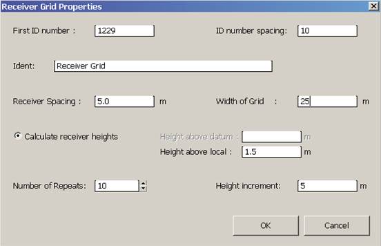
With the mouse, click where you want the top of the receiver grid to be positioned and then move to the bottom of the grid area and click again. The following dialogue box will appear. Here, you set the spacing of the receptor points on the grid (say 5 m) and the width of the grid. The value offered will provide a square grid, spaced equally each side of the line you drew. Select the smallest grid width to suit your needs, as otherwise calculation may be slow.
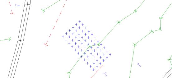
Select Calculate receiver heights. Height above local will be the height of the lowest layer of grid points. Then choose a suitable number of repeats. Each repeat generates another layer of grid points above the previous one. The height between each layer is set by the value Height Increment. The values shown in the dialogue box are typical and produced the grid shown below.
When you are satisfied, you should save the changes. If you are not satisfied, then Undo will get rid of the grid and you can try again. Step Two – Calculate the receiver grid noise levels Click on the Select tool (the button with the arrow on the toolbar) and drag around the receiver grid to select it. Then go to Calculate, Selected Receivers and run the calculation. This could take time if it is a large grid with many layers.
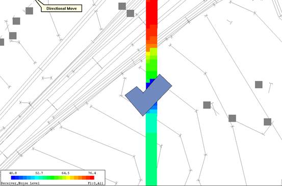
Step Three – View the results in colour Now go to View, Options and select View Receivers as Filled Squares. Set the size to large. When you exit this dialogue, you will see the grid is filled in solid blue. Now, you want to colour the receiver squares according to the noise level. Go to View, View-as-colour and set View as colour to On. In Object type to colour, select Receivers
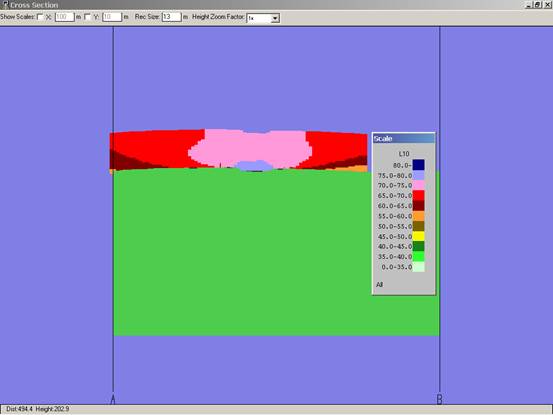
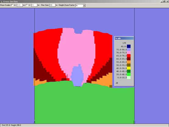
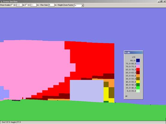
Step Four – Generate the cross-section To view the vertical noise contours, you need to generate a cross-section. Select Calculate, Draw Cross-Section, click at one end of the cross-section, move to the other end and click again. Click again to terminate drawing the cross-section line. Choose the method of getting ground heights in the cross-section and also select Colour receivers re noise level. (This option only appears when you have calculated the receiver noise levels). You should also choose the category of the result to be viewed, from the drop-down list of categories in your model. Click OK. The cross-section will be drawn and the receivers will appear as coloured squares. Initially, these are one metre square and depending on your grid spacing, you will probably need to make them bigger if you want a continuous contour. Enter the size of the squares in the Rec Size box at the top of the cross-section viewer window. For a five-metre grid spacing, a 5 m box size should just be enough, although if the cross-section line is not aligned with the grid, then some grid points may not be displayed. You may need to increase the receiver size further. Note that you can re-size the Cross-section window and you can zoom in and out with the page up and page down keys. You can scroll horizontally and vertically with the cursor keys. Step Five – Saving your vertical contour. To save a vertical contour, use the Windows Print Screen function.
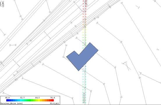
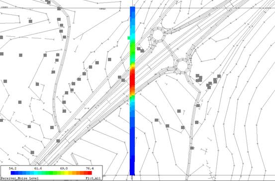
VERTICAL CONTOUR EXAMPLES
|
phone: +44 (0) 20 3355 9734 |
email: info@noisemap.com |